In lesson 15, you learnt how charged rods attract each other or small bits of
paper. You might have also played with magnets – the substances having the
property of attracting small bits of iron. But did you ever think of some relation
between electricity and magnetism? Such a relationship was discovered by
Oersted in 1820. Now we know, for sure, how intimately magnetism and
electricity are related.
In this lesson, you will learn the behaviour of magnets and their uses as also the
magnetic effects of electric current. The behaviour of current carrying conductors
and moving charges in a magnetic field are also discussed. On the basis of these
principles, we will discuss the working of electric devices like motors and
measuring devices like an ammeter, a voltmeter and a galvanometer.
OBJECTIVES
After seen this video, you should be able to :
- define magnetic field and state its SI unit;
- list the elements of earth’s magnetic field and write the relation between
- them;
- describe the magnetic effect of electric current : Oersted’s experiment;
- state Biot-Savart’s law and explain its applications;
- explain Ampere’s circuital law and its application;
- describe the motion of a charged particle in uniform electric field and magnetic field;
- explain the construction and working of a cyclotron;
- derive an expression for the force experienced by a current carrying conductor
- placed in a uniform magnetic field;
- derive an expression for the force between two infinitely long current carrying
- conductors placed parallel to each other; and
- explain the working principle of a galvanometer, an ammeter and a voltmeter
18.1 MAGNETS AND THEIR PROPERTIES
The phenomenon of magnetism was known to Greeks as early as 600 B.C. They observed that some stones called magnetite (Fe3 O4 ) attracted iron pieces. The pieces of naturally occurring magnetite are called natural magnets. Natural magnets are weak, but materials like iron, nickel, cobalt may be converted into strong permanent magents. All magnets–natural or artificial – have same properties. You must be familiar with basic properties of magnets. However, for completeness, we recapitulate these.
(i) Directive Property : A small bar magnet, when suspended freely on its
center of mass so as to rotate about a vertical axis, always stays in
approximately geographical north-south direction.
(ii) Attractive Property : A magnet attracts small pieces of magnetic materials
like iron, nickel and cobalt. The force of attraction is maximum at points
near the ends of the magnet. These points are called poles of the magnet. In
a freely suspended magnet, the pole which points towards the geographical
north is called is north pole and the one which points towards the
geographical south is called south pole. Do directive and attractive properties
suggest that our earth also acts like a magnet? Yes, it does.
(iii) Unlike poles of two magnets attract each other and like poles repel (Fig.18.1).
(iv) The poles of a magnet are inseparable, i.e. the simplest specimen providing
magnetic field is a magnetic dipole.
(v) When a magnet is brought close to a piece of iron, the nearer end of the
piece of iron acquires opposite polarity and the farther end acquires same
polarity. This phenomenon is called magnetic induction.

18.1.1 Magnetic Field Lines
Interactions between magnets or a magnet and a piece of iron essentially represent
action at a distance. This can be understood in terms of magnetic field. A very
convenient method to visualize the direction and magnitude of a field is to draw
the field lines :
- The direction of magnetic field vector B at any point is given by the tangent to the field line at that point.
- The number of field lines that pass through unit area of a surface held perpendicular to the lines is proportional to the strength of magnetic field in that region. Thus, the magnetic field B is large where the field lines are closer together and smaller where they are far apart.

Fig 18.2 shows a certain number of field lines passing through parallel surfaces S1 and S2 . The surface area of S1 is same as that of S2 but the number of field lines passing through S1 is greater than those passing through S2 . Hence, the number of lines per unit area passing through S1 is greater than that through S2 . We can, therefore, say that the magnetic field in the region around P is stronger than that around Q.
- Outside the magnet, the field lines run from north pole to south pole and inside it, these run from south pole to north pole forming closed curves (Fig.18.3).
- Two magnetic field lines can never cross each other.

INTEXT QUESTIONS 18.1
1.You are given a magnet. How will you locate its north pole.
- You are provided two identical looking iron bars. One of these is a magnet.
Using just these two, how will you identify which of the two is a magnet. - You are given a thread and two bar magnets. Describe a method by which
you can identify the polarities of the two magnets.

ACTIVITY 18.1
Let us perform an experiment with a magnetic needle. (You can actually perform
the experiment with a globe containing a bar magnet along its axis of rotation
with north pole of the magnet pointing south.) Suspend the needle freely in
such a manner that it can rotate in horizontal as well as vertical planes. If the
needle is near the equator on earth’s surface, it rests in horizontal plane. Suppose
this needle is taken to places in the northern hemisphere. The needle rotates in
the vertical plane and the north pole dips towards the earth, as we move towards
geographical north pole. Finally at a point very near to Hudson bay in Canada,
the north pole of the needle will point vertically downward. This place, located
at 6º east of north, is considered to be the south pole of the earth’s magnet.
This place is about 650 km away from the earth’s geographical north pole. Magnetism
If we take the same magnetic needle to places in the southern hemisphere,
the south pole of the needle will dip downward and point vertically
downward at a point 650 km west of the geographical south. This point
could be considered as the N pole of the earth’s magnet. From this we
conclude that the magnetic axis of the earth does not coincide with the
geographical axis.
An important aspect of earth’s magnetic field is that it does not remain constant;
its magnitude and direction change with time.
Elements of the Earth’s Magnetic Field
Three measurable quantities are used to describe the magnetic field of earth. These are called elements of earth’s magnetic field :
(a) Inclination or dip (δ);
(b) Declination (θ); and
(c) Horizontal component of the earth’s field (BM).
(a) Inclination or Dip
If you suspend a magnetic needle freely at a place, you will observe that the needle does not rest in the horizontal plane. It will point in the direction of the resultant intensity of earth’s field.

Fig. 18.5 shows the plane PCDE, which is the magnetic meridian at the point P (i.e. the vertical plane passing through the north and south poles of the earth’s magnet) on the surface of the earth and PABC is the geographic meridian (i.e. the vertical plane passing through the geographical north and south poles of the earth). Suppose that PR represents the magnitude and direction of the earth’s magnetic field at the point P. Note that PR makes an angle δ with the horizontal direction. This angle is known as inclination or dip at P on the surface of the earth.
The angle which the earth’s magnetic field makes with the horizontal direction
in the magnetic meridian is called the dip or inclination.
(b) Declination
Refer to Fig 18.5 again. The plane PCDE contains the magnetic field vector (PR) of the earth. The angle between the planes PCDE and PABC is called the declination at the point P. It is shown as angle θ.
The angle which the megnetic meridian at a place makes with the geographical meridian is called the declination at that place.e declination at that place.
(c) Horizontal component
Fig. 18.5 shows that PR is the resultant magnetic field at the point P. PH represents the horizontal component and PF the vertical component of the earth’s magnetic field in magnitude and direction. Let the magnetic field at the point P be B. The horizontal component
BH = B cos δ
and the vertical component
BV = B sin δ
By squarring and adding Eqns. (18.1) and (18.2), we get
BH2 + BV2 = B2 cos2 δ + B2 sin2 δ = B2
On dividing Eqn. (18.2) by Eqn. (18.1), we have
BV/BH = tan δ
18.2 ELECTRICITY AND MAGNETISM : BASIC CONCEPTS
You now know that flow of electrons in a conductor due to a potential difference across it constitutes electric current. The current flowing in a conductor is seen to exert a force on a free magnetic needle placed in a region around it. A magnetic needle is also affected by a magnet and hence we say that a current carrying conductor has a magnetic field around it. The magnetic field B is visualized by magnetic field lines. You will learn about these and some more terms such as magnetic permeability later in this lesson.
18.2.1 Magnetic Field around an Electric Current
Let us do a simple experiment.
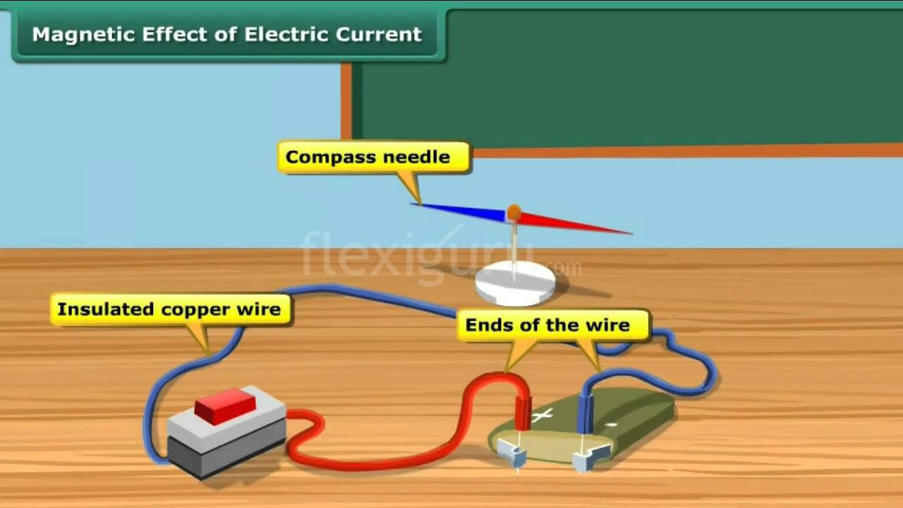
ACTIVITY 18.2
Take a 1.5 volt battery, a wire about 1 m in length, a campass needle and a match box. Wind 10-15 turns of the electric wire on its base. Under the windings, place a campass needle, as shown in Fig. 18.6. Place the match box on the table so as to have the wires running along the north – south direction. Connect the free ends of the wire to the battery. What happens to the needle? You will observe that needle shows deflection. This means that there is a magnetic field in and around the coil. The deflection will reverse if you reverse the direction of current by changing the terminals of the battery. When there is no

current in the wire, the compass needle points in the north – south direction (Fig. 18.7 a, b & c). When a magnetic needle is brought close to a vertical current carrying wire, the magnetic field lines are concentric circles around the wire, as shown in Fig 18.7 (d).

In 1820 Hans Christian Oersted, Professor of Physics at Copenhaegen in Denmark performed similar experiments and established that there is a magnetic field around a current carrying conductor.
18.3 BIOT-SAVART’S LAW
Biot-Savart’s law gives a quantitative relationship between current in conductor and the resulting magnetic field at a point in the space around it. Each part of a current carrying conductor contributes to magnetic field around it. The net value of B at a point is thus the combined effect of all the individual parts of the conductor. As shown in Fig. 18.8, the net magnetic field due to any current carrying conductor is the vector sum of the contributions due to the current in each infinitesimal element of length Δl .
Experiments show that the field B due to an element Δl depends on
– current flowing through the conductor, I;
– length of the element Δl ;
– inversely proportional to the square of the distance of observation point
P from the element Δl ; and
– the angle between the element and the line joing the element to the
observation point.
Thus, we can write

Direction of B : Magnetic field at a point is a vector quantity. The direction of B may be determined by applying the right hand grip rule. To apply this rule, let us consider the direction of the field produced in some simple cases. As shown in the Fig. 18.9 (a), grasp the wire in your right hand so that the thumb points in the direction of the current. Then the curled fingers of the hand will point in the direction of the magnetic field. To represent the magnetic field on paper, let us consider that current is flowing into the plane of the paper. Then according to the right hand rule, the field lines shall be in the plane of the paper (Fig.18.9 b).


18.3.1 Applications of Biot-Savart’s Law
You now know that Biot-Savart’s law gives the magnitude of the magnetic field. Let us now apply it to find the field around conductors of different shapes. Note that to calculate the net field due to different segments of the conductor, we have to add up the field contributions due to each one of them. We first consider a circular coil carrying current and calculate magnetic field at its centre.
(a) Magnetic field at the centre of a circular coil carrying current : Refer to Fig.18.10. It shows a circular coil of radius r carrying current I. To calculate magnetic field at its centre O, we first consider a small current element Δ l of the circular coil. Note that the angle between current element Δl and r is 90º. From Eqn. (18.5) we know that the field at the centre O due to Δl is

The direction of ΔB is normal to the plane of the coil. Since the field due to every element of the circular coil will be in the same direction, the resultant is obtained by adding all the contributions at the centre of the loop. Therefore

In case there is more than one loop of wire (say there are n turns), the field is given by

You can check the direction of the net field using the rule given in Fig. 18.7. You can use right hand rule in any segment of the coil and will obtain the same result. (Another simple quick rule to identify the direction of magnetic field due to a current carrying coil is the so called End-rule, illustrated in Fig. 18.11 (a, b).

When an observer looking at the circular coil at its either end finds the current to be flowing in the clockwise sense, the face of the coil behaves like the south pole of the equivalent magnet, i.e., B is directed inwards. On the other hand, if the current is seen to flow in the anticlockwise sense, the face of the coil behaves like the north pole of the equivalent magnet or the field is directed out of that end.
INTEXT QUESTIONS 18.2
1. What can you say about the field developed by
(i) a stationary electron ?
(ii) a moving electron ?
2. Electrons in a conductor are in constant motion due to thermal energy. Why do they not show magnetism till such time that a potential difference is applied across it ?
3. A current is flowing in a long wire. It is first shaped as a circular coil of one turn, and then into a coil of two turns of smaller radius. Will the magnetic field at the centre coil change? If so, how much ?
18.4 AMPERE’S CIRCUITAL LAW
Ampere’s circuital law provides another way of calculating magnetic field around a current carrying conductor in some simple situations.
Ampere’s circuital law states that the line integral of the magnetic field B around a closed loop is μ0 times the total current, I. Mathematically, we write


Note that this is independent of the size or shape of the closed loop.


(b) Magnetic field due to a solenoid
A solenoid is a straight coil having a large number of loops set in a straight line with a common axis, as shown in Fig. 18.14. We know that a current I flowing through a wire, sets up a magnetic field around it. Suppose that the length of the solenoid is l and it has N number of turns. To calculate the magnetic field inside the solenoid along its axis (Fig 18.14), we can treat it to be a section of a toroidal solenoid of a very large radius. Thus :

|B| = μ0 nI
The direction of the field is along the axis of the solenoid. A straight solenoid is finite. Therefore, |B| = μ0 nI should be correct well inside the solenoid, near its centre.
For solenoids of small radius, the magnitude of B at the ends is given by

18.4.2 Application of Ampere’s Circuital Law
(b) Magnetic Field due to a Straight Solenoid
A solenoid is a straight coil having a large number of loops set in a straight line with a common axis, as shown in Fig. 18.4.2. We know that a current I flowing through a wire, sets up a magnetic field around it. Suppose that the length of the solenoid is A and it has N number of turns.
The magnetic field inside the solenoid, in its middle, is uniform and parallel to its axis. Outside the solenoid, however, the field is negligibly weak. These statements hold true, strictly speaking, if the length of the solenoid is very large as compared to its diameter. For a long solenoid, whose windings are very tightly and uniformly wound, the magnetic field inside it is fairly uniform everywhere and is zero outside it.

Let us take a rectangular loop abcd as shown in Fig 18.4.2. Along the path ab, the magnetic field is uniform. Hence, for this path B.dA = BA. Along the paths cd, as the magnetic field is weak it may be taken as zero. Hence, for this path B.dA = 0. The two short sides bc and da also do not contribute anything to B.dA as B is either zero (outside the solenoid), or perpendicular to dA (inside the solenoid).
If n be the number of turns per unit length along the length of the solenoid, then the number of turns enclosed by the rectangular loop of length A is nA. If each turn of the solenoid carries a current i, then the total current threading the loop is nAi. Hence, from Ampere’s circuital law,

(c) Magnetic field due to a toroid
A toroid is basically an endless solenoid which may be formed by bending a straight solenoid so as to give it a circular shape.

Suppose, we want to find the magnetic field at a point P, inside the toroid, whose distance from the centre O is r. Draw a circle passing through the point P and concentric with the toroid. The magnetic field will everywhere be tangential to the circle, its magnitude being the same at all points of it. So, we can write:

18.4.3 Electromagnets and Factors Affecting their Strength
We have seen that a current-carrying solenoid behaves as a bar magnet, with one end behaving as north pole and the other as south pole depending on the direction of flow of current. The polarity of such magnets is determined by the end rule and the strength of the magnetic field is given by
|B| = μ nI
where 0μ is the permeability of free space, n is the number of turns per unit length and I is the current flowing through the solenoid.
It is clear that the solenoid remains a magnet as long as the a current is flowing through it. Thus, a current-carrying solenoid is called an electromagnet. Its strength depends on :
(i) Number of turns per unit length of the solenoid, and
(ii) The current flowing through it. It may also be noted that the strength of the magnetic field of an electromagnet increases when a soft iron core is introduced inside it.
18.4.4 Concept of Displacement Current
The concept of displacement current was introduced by Maxwell. As we know, magnetic field is produced due to the conduction current. However, according to Maxwell in empty space (where no conduction current exists), the magnetic field is produced due to the displacement current which, unlike conduction current, is not associated with the motion of charges.
Consider a simple circuit consisting of a small parallel-plate capacitor being charged by a current I.

However, applying Ampere’s circuital law to the contour C and the surface S2, as there is no current through this surface, we get
∫ B⋅ = dA 0
The above two equations are mutually contradictory. To avoid this contradiction, Maxwell assumed that a current exists between the capacitor plates. He called this current displacement current and showed that this current arises due to the variation of electric field with time.
A simple expression for the displacement current can be derived as follows. Consider a parallel plate capacitor. Let q be the charge on the capacitor plates at any instant t.
The electric field inside the capacitor is given by

Example 18.1 : A 50 cm long solenoid has 3 layers of windings of 250 turns each. The radius of the lowest layer is 2cm. If the current through it is 4.0 A,
calculate the magnitude of B (a) near the centre of the solenoid on and about the axis; (b) near the ends on its axis; and (c) outside the solenoid near the middle.
Solution :

INTEXT QUESTIONS 18.3
1. A drawing of the lines of force of a magnetic field provides information on
a) direction of field only
b) magnitude of field only
c) both the direction and magnitude of the field
d) the force of the field
2. What is common between Biot-Savart’s law and Ampere’s circuital law ?
3. In the following drawing of lines of force of a non-unifrom magnetic field, at which piont is the field (i) uniform, (ii) weakest, (iii) strongest?

4. A 10 cm long solenoid is meant to have a magnetic field 0.002T inside it, when a current of 3A flows through it. Calculate the required no. of turns.
5. Derive an expression for the field due to a toroid using Ampere’s circuital law.
18.5 FORCE ON A MOVING CHARGE IN A MAGNETIC FIELD
When a charged body moves in a magnetic field, it experiences a force. Such a force experienced by a moving charge is called the Lorentz force. The Lorentz force on a particle with a charge +q moving with a velocity v in a magnetic field B is given by
F = q (v × Β )
or |F| = q v B sin θ
where θ is the angle between the directions of v and B. The direction of F is given by Fleming’s left hand rule.

Fleming’s left hand rule states that if we stretch the fore finger, the central finger and the thumb of our left hand at right angles to each other and hold them in such a way that the fore finger points in the direction of magnetic field and the central finger points in the direction of motion of positively charged particle, then the thumb will point in the direction of the Lorentz force (Fig. 18.17).
Some important points to note
- F is a mechanical force resulting in a pull or a push.
- The direction of force is given by Fleming’s left hand rule.
- In case of negative charges, the central finger should point opposite to the direction of its motion.
- If the charge stops, the force becomes zero instantly.
- Force is zero when charges move along the field B.
- Force is maximum when charges move perpendicular to the field : F = qvB
18.5.1 Force on a Current Carrying Conductor in a Uniform Magnetic Field
The concept of Lorentz force can be easily extended to current carrying conductors placed in uniform magnetic field B. Suppose that the magnetic field is parallel to the plane of paper and a conductor of length Δl carrying current I is placed normal to the field. Suppose further that the current is flowing downward with a drift velocity vd and hence each free electron constituting the current experiences a Lorentz force F = e vd . B
If there are N free electrons in the conductor, the net force on it is given by

The direction of the force is again given by Fleming’s left hand rule.
Eqn. (18.12) can be used to define the unit of magnetic field in terms of the force experiencd by a current carrying conductor. By rearranging terms, we can write

18.5.2 Force Between two Parallel Wires Carrying Current
You now know that every current carrying conductor is surrounded by a magnetic field. It means that it will exert force on a nearby current carrying conductor. The force between two current carrying conductors placed parallel to each other is mutual and magnetic in origin. A current carrying wire has no net electric charge, and hence cannot interact electrically with another such wire.

Fig 18.19 shows two parallel wires separated by distance r and carrying currents

18.5.3 Motion of a Charged Particle in a Uniform Field
We can now think of various situations in which a moving charged particle or a current carrying conductor in a magnetic field experiences Lorentz force. The work done by a force on a body depends on its component in the direction of motion of the body. When the force on a charged particle in a magnetic field is perpendicular to its direction of motion, no work is said to be done. Hence the particle keeps the same speed and kinetic energy which it had while moving in the field, even though it is deflected. On the other hand, the speed and energy of a charged particle in an electrical field is always affected due to the force by the field on the particle. A charged particle moving perpendicular to a magnetic field follows a circular path (Fig. 18.20) because it experience a force at right angles to the direction of motion at every position.

To know the radius R of the circular path of the charged particle, we note that the magnetic force q υ B provides the particle with the centripetal force (m υ2 /R) that keeps it moving in a circle. So we can write

The radius of the path traced by a charged particle in a uniform magnetic field is directly proportional to its momentum (mv) and inversely proportional to its charge and the magnetic field. It means that greater the momentum, larger the circle, and stronger the field, the smaller the circle. The time period of rotation of the particle in a circular path is given by

Note that the time period is independent of velocity of the particle and radius of the orbit. It which means that once the particle is in the magnetic field, it would go round and round in a circle of the same radius. If m, B, q, remain constant, the time period does not chnage even if v and R are changed.
Now think, what happens to R and T if a) field B is made stronger; b) field B is made weaker; c) field B ceases to exist; d) direction of B is changed; d) the particle is made to enter the magnetic field at a higher speed; f) the particle enters at an angle to B; and g) the charged particle loses its charge.
18.5.4 Motion of a Charged Particle in uniform Electric Field and Magnetic Field
(a) Motion in Electric Field
When a charged particle q is placed in a uniform electric field E, it experiences a force,
F = qE
Thus, the charged particle will be accelerated under the influence of this force. The acceleration is given by

The acceleration will be in the direction of the force. If it is a positive charge, it will accelerate in the direction of the field and if it is a negative charge it will
accelerate in a direction opposite that of the field. The velocity and displacement of charged particle can also be calculated by using the equations of motion:

(b) Motion in magnetic field
In article 18.5 (Page 114, Book 2), it has been discussed that the force experienced by a charged particle in a magnetic field is given by
F = qBνsinθ
Where θ is angle between the velocity and magnetic field.
If θ = 0, F = 0 and charged particle will move along a straight line with constant speed.
If θ = 90°, F will be maximum and its direction, according to Fleming’s left hand rule, will be perpendicular to the plane of v and B and the charged particle will move along a circular path with a constant speed and frequency.
If θ ≠ 0° ≠ 90°, then the velocity of the charged particle will be vsinθ perpendicular to the field and vcosθ parallel to the field. The particle, therefore, moves along a helical path.
What we note from the above discussion is that a magnetic field does not change the speed of a moving charge, it only changes its direction of motion.

18.5.5 Cyclotron
The cyclotron is a device invented by E.O. Lawrence in 1929, that is used for accelerating charged particles (such as protons, deutron or α–particles) to high velocities. It consists of two semi-circular hollow metallic disks DD, called dees, on account of their shape resembling the letter D of English alphabet. They are insulated from one another with a small gap between them. The dees are placed in an evacuated chamber.

A magnetic field perpendicular to the plane of the dees (out of the paper in Fig) is maintained with the help of an electromagnet having flat pole–pieces. A rapidly oscillating potential difference is applied between the dees with the help of an oscillator. This produces an oscillating electric field in the gap between the dees.
Consider a charged particle of mass m and charge q in the gap between the dees. The particle is accelerated by the electric field towards one of them. Inside the dees, it moves with constant speed in a semicircle in a clockwise direction. If the frequency of the oscillator is equal to the frequency of revolution of the charged particle, then it reaches the gap at the instant when the opposite dee becomes negative because of the reversal of the direction of electric field.
The frequency of revolution of the charged particle is given by (see Eq. 18. 14a):

It is also called cyclotron frequency and denoted by vC. When vC = vO, the frequency of the oscillator, the particle reaches the gap when the electric potential at the opposite ‘D’ has just reversed its sign. This condition is also known as cyclotron resonance condition. On account of this, the particle gains energy and, therefore, it moves in a circle of larger radius. This energy gain can be repeated many times.
Thus, the energy and the radius of the path of the particle keep on increasing progressively. However, the maximum radius which the path can have is limited by the radius R of the dees. The high energy charged particle finally comes out through an opening in the dee.
Example 18.3 : Refer to Fig. 18.21 and calculate the force between wires carrying current 10A and 15A, if their length is 5m. What is the nature of this force ?
Solution : When currents flow in two long parallel wires in the same direction, the wires attract each other and the force of attraction is given by


Example 18.4 : An electron with velocity 3 ×10⁷ ms-1 describes a circular path in a uniform magnetic field of 0.2T, perpendicular to it. Calculate the radius of the path.
Solution :

INTEXT QUESTION 18.4
1. A stream of protons is moving parallel to a stream of electrons but in the opposite direction. What is the nature of force between them ?
2. Both electrical and magnetic fields can deflect an electron. What is the difference between them?
3. A body is suspended from a vertical spring. What shall be the effect on the position of the body when a current is made to pass through the spring.
4. How does a cyclotron accelerate charged particles?
18.6 CURRENT LOOP AS A DIPOLE
From Eqn. (18,6) you will recall that the field at the centre of a coil is given by


ACTIVITY 18.3
Suspend a bar magnet by a thread between pole pieces of a horse shoe magnate, as shown in Fig 18.22.

What will happen when the bar magnet shown in Fig. 18.24(a) is displaced slightly sideways? Since like poles repel, the bar magnet experiences a torque and tends to turn through 180º and get aligned, as shown in Fig. 18.22 (b). Since a current loop behaves as a magnet, it will align in an external field in the same way.
You have already studied the following equations in the lesson on electrostatics. The electric field of a dipole at a far point on its axis is given by

A comparison between these expressions leads us to the following analogies :
- A current loop behaves as a magnetic dipole with magnetic moment
M = NIA
- Like the poles of a magnetic dipole, the two faces of a current loop are inseparable.
- A magnetic dipole in a uniform magnetic field behaves the same way as an electric dipole in a uniform electric field.
- A magnetic dipole also has a magnetic field around it similar to the electric field around an electric dipole.
Thus magnetic field due to a magnetic dipole at an axial point is given by


18.6.1 Torque on a Current Loop
A loop of current carrying wire placed in a uniform magnetic field (B) experiences no net force but a torque acts on it. This torque tends to rotate the loop to bring its plane perpendicular to the field direction. This is the principle that underlines the operation of all electric motors, meters etc.
Let us examine the force on each side of a rectangular current carrying loop where plane is parallel to a uniform magnetic field B. (Fig. 18.24 (a).)


coil were always along or parallel to the magnetic field. This is achieved by making the pole pieces of the magnet curved and placing a soft iron core at the centre so as to give a radial field.

The soft iron core placed inside the loop would also make the magnetic field stronger and uniform resulting in greater torque (Fig. 18.26).
18.6.1 (a) Magnetic Dipole
The term magnetic dipole includesa
(i) current-carrying circular coil of wire, and
(ii) a small bar magnet
The magnetic field due to a magnetic dipole at a point
(i) situated at a distance r on the axis of the dipole is given by :

18.6.1(b) The Torque on a Magnetic Dipole Placed in a uniform magnetic field

18.6.2 Galvanometer
From what you have learnt so far, you can think of an instrument to detect current in any circuit. A device doing precisely this is called a galvanometer, which works on the principle that a current carrying coil, when placed in a magnetic field, experiences a torque.
A galvanometer consists of a coil wound on a non-magnetic frame. A soft iron cylinder is placed inside the coil. The assembly is supported on two pivots attached to springs with a pointer. This is placed between the pole pieces of a horse shoe magnet providing radial field (see Fig. 18.27).

To understand the working of a moving coil galvanometer, we recall that when a current is passed through the coil, it will rotate due to the torque acting on it. The spring sets up a restoring force and hence, a restoring torque. If α is the angle of twist and k is the restoring torque per unit twist or torsional contant, we can write NBIA sinθ = k α. For θ = 90º, sinθ = 1. So, in the instant case, we can write

That is, deflection produced in a galvanometer is proportional to the current flowing through it provided N, B A and k are constant. The ratio α/I is known as current sensitivity of the galvanometer. It is defined as the deflection of the coil per unit current. The more the current stronger the torque and the coil turns more. Galvanometer can be constructed to respond to very small currents (of the order of 0.1μA).
Sensitivity of a galvanometer : In order to have a more sensitive galvanometer,
- N should be large;
- B should be large, uniform and radial;
- area of the coil should be large; and
- tortional constant should be small.
The values of N and A cannot be increased beyond a certain limit. Large values of N and A will increase the electrical and inertial resistance and the size of the galvanometer. B can be increased using a strong horse shoe magnet and by mounting the coil on a soft iron core. The value of k can be decreased by the use of materials such as quartz or phospher bronze.
18.6.3 An Ammeter and a Voltmeter
a) Ammeter : An Ammeter is a suitably shunted galvanometer. Its scale is calibrated to give the value of current in the circuit. To convert a galvanometer into an ammeter, a low resistance wire is connected in parallel with the galvanometer. The resistance of the shunt depends on the range of the ammeter and can be calculated as follows :
Let G be resistance of the galvanometer and N be the number of scale divisions in the galvanometer. Let k denote figure of merit or current for one scale deflection in the galvanometer. Then current which produces full scale deflection in the galvanometer is Ig= Nk
Let I be the maximum current to be measured by the galvanometer.
Refer to Fig. 18.28. The voltage between points A and B is given by

As G and S are in parallel, the effective resistance R of the ammeter is given by

As the shunt resistance is small, the combined resistance of the galvanometer and the shunt is very low and hence, ammeter resistance is lower than that of the galvanometer. An ideal ammeter has almost negligible resistance. That is why when it is connected in series in a circuit, all the current passes through it without any observable drop.
(b) Voltmeter : A voltmeter is used to measure the potential difference between two points in a circuit. We can convert a galvanometer into a voltmeter by connecting a high resistance in series with the galvanometer coil, as shown in Fig 18.29. The value of the resistance depends on the range of voltmeter and can be calculated as follows :

A high resistance, say R is connected in series with the galvanometer coil. If the potential difference across AB is V volt, then total resistance of the voltmeter will be G + R. From Ohm’s law, we can write

any current. But the galvanometer coil deflects. Seems impossible! Think about it.
Example 18.6 : A circular coil of 30 turns and radius 8.0 cm, carrying a current of 6.0 A is suspended vertically in a uniform horizontal magnetic field of magnitude 1.0 T. The field lines make an angle of 90º with the normal to the coil. Calculate the magnitude of the counter torque that must be applied to prevent the coil from turning.


Thus, a resistance of 3988 Ω should be connected in series to convert the galvanometer into voltmeter.
INTEXT QUESTIONS 18.5
1. What is radial magnetic field ?
2. What is the main function of a soft iron core in a moving coil galvanometer?
3. Which one has the lowest resistance – ammeter, voltmeter or galvanometer? Explain.
4. A galvanometer having a coil of resistance 20 Ω needs 20 mA current for full scale deflection. In order to pass a maximum current of 3A through the galvanometer, what resistance should be added and how ?
WHAT YOU HAVE LEARNT